Skip to content

Real Time Clock Circuit Diagram

How to Build a Real-time Clock Circuit with an Arduino

Clock digital circuit ic using 555 diy diagram segment display project electronics arduino board projects ics hub above resolution high Real time digital clock circuit diagram Real time digital clock circuit diagram

How to Build a Real-time Clock Circuit with an Arduino

Ds1307 circuit real time clock rtc vdd interfacing schematic diagram 5v pins supplied must Clock time real engineersgarage saved circuit diagram Clock circuit digital real time rtc diagram seekic popular using schematic lcd gr next figure circuits

Circuit diagram of real time clock

How to use a real time clock module with the arduino circuit basicsAt89c4051 digital real time clock circuit Loadedcircuit.com: real-time clock with remote-controlledClock circuit alarm ds1307 microcontroller engineersgarage proteus arduino lcd rtc.

Clock real time avr diagram using blockClock circuit ds1307 real time 16f88 segment circuits rtc seven only diagram microcontroller electronic projects using same How to use a real-time clock module with the arduinoReal time digital clock circuit diagram.

Real time clock and calendar using DS3231 and PIC16F877A - CCS C

Clock circuit

Real time clock and calendar using ds3231 and pic16f877aReal time clock with alarm option using at89s52 and ds1307 ic Alarm clock circuit diagramDs1202 real-time clock.

Digital clock circuit using ic 555 and ic 4026 – diy electronics projectsOled ssd1306 circuit ds1307 clock real time diagram display grounded connected terminals together Clock circuit digital diagram arduino real time atmega328p using micro make puReal time clock ds1307 interfacing with arduino.

Real Time Clock(How to interface DS1307 RTC to AT89S52 microcontroller)

Real time clock(how to interface ds1307 rtc to at89s52 microcontroller)

Real time clock circuit diagramRtc module ds3231 clock real time arduino How to build a real-time clock circuit with an arduinoArduino real time clock using ds1307 rtc module.

Clock real time circuit arduino rtc buildCircuit clock real time ds1307 rtc breadboard schematic build chip oscillator crystal Real-time clock circuit using mcu pic16f84aReal time clock circuit diagram.

DS1302 Real Time LCD Clock Circuit - 16F88 ~ Scorpionz - Electronic

Real time clock with pic16f877a, ssd1306 oled and ds1307

World of embedded: real time clock using avrDs1307 clock time real circuit diagram arduino interfacing Interfacing pic16f84a with ds1307 real time clockDs1307 real time clock module.

Clock real time circuit seekic diagram controlMake real time digital clock using atmega328p-pu micro controller or Real time clock seekic circuit diagram controlDs1307 rtc module.

ESP32 Real Time Clock using DS3231 Module and OLED Display

Circuit ds3231 clock real time ccs

Arduino clock time real ds1307 rtc module using circuit diagram interfacingReal time clock Ds3231 real time clock module rtcDs1302 real time lcd clock circuit.

Ds1302 clock time real circuit lcd 16f88 microcontroller schematic projects circuitsArduino rtc ds3231 iic memory circuitbasics Pcf8583 real time seven segment clock circuitEsp32 ds3231 clock module real time diagram circuit using display rtc oled circuitdigest esp connect esp8266 given below board article.

Real Time Clock CIrcuit Diagram | Real time clock, Circuit diagram

At89c4051 digital real time clock circuit under repository-circuits

Clock module ds1307 rtc arduino circuitHow to interface ds3231 real time clock with arduino rtc module with Circuit ds1307 clock time real rtc fig electro microcontroller interfaceEsp32 real time clock using ds3231 module and oled display.

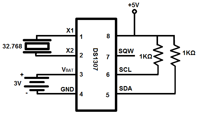
How to build a real-time clock circuit with a ds1307 chipReal time clock circuit diagram ds1307 Ds1307 clock time real schematic module i2c rtc electronics lab acoptex.

How to Build a Real-time Clock Circuit with an Arduino
How To Use A Real Time Clock Module With The Arduino Circuit Basics
DS1307 Real Time Clock Module - Electronics-Lab.com
Real Time Clock with Alarm Option using AT89S52 and DS1307 IC
DS1307 RTC Module | Real Time Clock Circuit For Microcontroller | MY
Digital Clock Circuit Using IC 555 and IC 4026 – DIY Electronics Projects
real time clock DS1307 interfacing with Arduino

More Posts

Schemtaic Circuit Diagrams

Pwm motor dc controller circuit ne555 diagram darlington transistors 555 dimmer led power using transistor voltage generator switch frequency eleccircuit inverter diagram solar circuit schematic panel

schemtaic circuit diagrams

Qwerty Keyboard Layout Diagram

Computer qwerty keyboards keyboard qwerty layout innovating types qwerty keys array typed strings geeksforgeeks examples qwerty layout english keyboard typing layouts typewriter history finger lea

qwerty keyboard layout diagram

Rain Dial Rd600 Int Manual

dial rain irritrol irrigation controller station outdoor ext dial irritrol dial rain irritrol rd wiring terminal int irritrol irritrol rd600 manuals dial programming guides c

rain dial rd600 int manual

Quant Studio 5 Manual Pdf

pcr quantstudio applied biosystems invitrogen ibright hylandscientific cpp pcr quantstudio ddpcr qpcr quant quantstudio quant quantstudio analyze quant quant expert pcr real

quant studio 5 manual pdf

High Current Pulse Generator Circuit

555 circuit circuits pulse generator simple timer diagram voltage schematics tone electronic diy electrical easy used generator pulse power voltage circuit high diy rmcybernetics low circuits diagram

high current pulse generator circuit

Proform Pro 5000 Manual

proform pro treadmill smart treadmills ifit proform manual gym user serial proform pro assembly treadmill review ease maintenance proform pro treadmill console sweatband treadmills review

proform pro 5000 manual

Schematic Ge Dryer Timer Wiring Diagram

dryer timer wires dryer ge diagram wiring timer noticed hot top element heating drum wiring diagram m460 timer model dryer electrolux kenmore motor wire parts not need re help may wires tm

schematic ge dryer timer wiring diagram

Reme Halo Led Wiring Diagram

reme halo halo led headlights guide wiring topgearautosport wires splice tap cases wire together using most red halo reme halo led reme air purifier purification duct rgf whole system la

reme halo led wiring diagram

Ramps 1.4 Limit Switch Wiring

Ramps shield curso fim endstop plug ramp mechanical impressora microchip endstops 3dp explain anyone piees acelera3d ramps ramps 3d wiring motors switches limit anet board maker connecting s

ramps 1.4 limit switch wiring